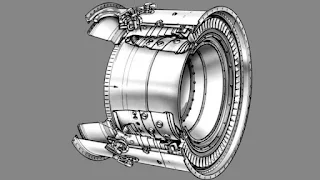
Combustors
A gas turbine engine's combustor is necessary for burning a
mixture of fuel and air and delivering the resulting gas mixture to the turbine
inlet at a temperature as uniform as feasible. A good combustion engine will
satisfy the following criteria:
- High efficiency:-fuel is burned almost entirely to ensure maximum energy release. Long range requires this.
- Stable operation:-must be blowout-free at mass flow values ranging from idle to maximum power and at pressures spanning the aircraft's whole altitude range.
- Low pressure loss:-Gases should be delivered to the turbine at their highest possible pressure to minimise pressure loss. When any cooling air travelling through the turbine re-enters the main air flow, some pressure loss is necessary to ensure the right direction of circulation.
- Uniform temperature distribution:-The gases from the combustor should enter the turbine as close to the limiting metal temperature as feasible to achieve maximum engine performance. To safeguard the engine, hot areas in the flow will lower the acceptable turbine inlet temperature. Additionally, this will lower engine performance.
- A well-designed combustor will be able to restart in flight over a wide range of altitudes and flight speeds.
- Simple starting (primarily air starts).
- Small size:- Engine capacity and diameter are directly influenced by combustor size. A high energy release rate in a tiny size is desired.
- Low smoke:- a smoky combustion chamber is only a minor nuisance. A smoke-producing burner could help locate military aircraft in flight.
- Low carbon formation:- Carbon buildup in the burner can obstruct vital air passages, raising metal temperatures above desired levels and shortening engine life.
Types of Gas Turbine Combustor
Combustors for
aircraft engines have developed into three basic types in order to satisfy
these requirements.
- Can combustor
- Annular combustor
- Can-annular combustor
The Can Type Combustor
Can combustors
have the drawback of not maximizing available space, which results in a huge
engine diameter. They have relatively substantial pressure losses and are very
hefty. The individual cans are simple to remove for inspection, and they allow
for easier control of the fuel-air patterns than annular designs do.
Annular Combustor
There are
drawbacks to the annular combustor as well. Because of the wide diameter and
thin walls, there can be structural issues. The complete combustor must be
taken out of the engine for inspection or significant repairs from a
maintenance perspective. Additionally vulnerable to combustion instability is
the annular combustor.
Can-annular combustor
The universal
traits present in all types of combustion processes serve as the basis for
combustor design. Whether contemplating combustion in a fireplace or a jet
engine, the needs resulting from these features are fundamental. them being:
(1) proper
mixture ratio
(2) temperature of the reactants
(3) turbulence
for good mixing and
(4) time for
burning.
Additionally,
the combustion process for aviation turbine engines must be completed with a
respectable pressure loss.
Any combustion
process must have a certain mixture ratio because there are lean and rich
flammability limits above which burning is impossible. In terms of fuel-air
ratio, the lean limit for JP-type fuels is approximately 0.04, and the rich
limit is approximately 0.20.
The
stoichiometric fuel-air ratio for the majority of hydrocarbon fuels is
approximately 0.0667. As a result, it is clear that any combustor must maintain
a mixture ratio that is within permissible limits if burning is to occur at
all, and within much stricter limits if good burning is to occur. It is
important to operate the combustor with a significant amount of extra air to
provide appropriate cooling in order to lower the temperature of the gases
leaving the combustor to an admissible value. The significant amount of extra
air needed lowers the overall fuel-air ratio to a value that is often less than
0.02. This fuel-to-air ratio is obviously too low for combustion, thus the
burner design must include a way to remove between 60 and 75 percent of the air
surrounding the actual combustion zone. The air that is bypassed is referred to
as secondary air because it does not participate in combustion, whereas the
remaining air, which does, is referred to as primary air. The amount of primary
air is dictated by the fuel-air ratio in the actual combustion zone.
Reverse-flow combustor
In Reverse-flow combustor air from the compressor enters the outer casing before flowing backward into the inner liner. As it enters the inner lining, it changes direction once more. Before passing past the turbine, it turns around once more. Where engine length is important, reverse-flow combustors are used.
Also Read
Resolver (Electrical) | Rotary Electrical Transformer | What is the purpose of a resolver?
Full Authority Digital Engine Control (FADEC) System Description & Operation


0 Comments